GD&T (Geometric Dimensioning and Tolerancing) defines the precise dimensions and tolerances of parts, ensuring design and manufacturing accuracy. So, what are datums in GD&T? In simple terms, datums serve as reference points or surfaces from which all other dimensions and measurements are taken. Understanding datums is key to achieving correct alignment, positioning, and assembly. As such, this guide will delve into the essential concepts of datums, covering their definitions, classification, and practical applications. Whether you’re new to GD&T or aiming to deepen your knowledge, this post will help you grasp the critical role datums play in ensuring part accuracy and successful assembly.
What is a Datum in GD&T?
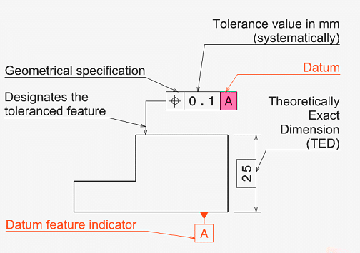
In GD&T, a datum refers to a reference point, line, or surface that serves as the origin for measuring and locating other features of a part. As such, it plays a critical role in ensuring precise alignment, orientation, and positioning during manufacturing and assembly. By providing a standardized starting point, a datum helps establish measurements and tolerances more effectively, ultimately facilitating consistency and accuracy throughout the entire process.
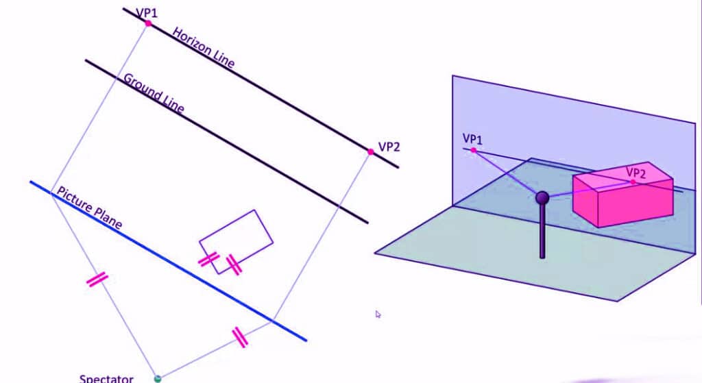
To better understand this, imagine manufacturing a car wheel axle. The axle has several features, such as holes and surfaces, that must align precisely. In this case, you would choose a flat surface on the axle as the datum. From this point, other features, like holes and connection points, are measured relative to the datum to ensure proper alignment and assembly.
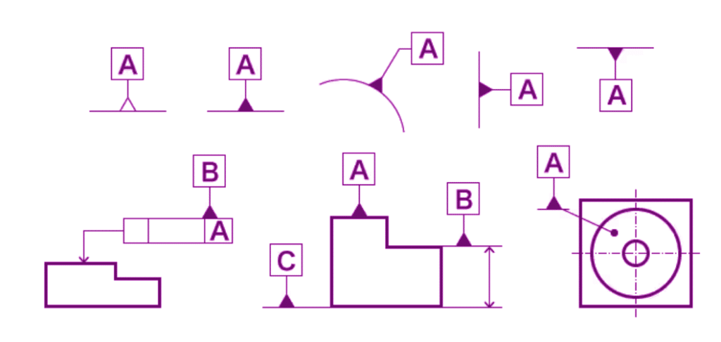
Furthermore, datums can rely on features such as holes or surfaces, or on datum targets for irregular shapes. In engineering drawings, datums are marked with specific symbols to show the required alignment.
Key standards that guide the use of datums include:
- ASME Y14.5-2018, which outlines how to establish and reference datums.
- ISO 1101:2017, which provides international guidelines for geometrical tolerancing.
- ASME B89.3.1-2021, which explains how datums are used in CMM calibration.
Classification and Notation of Datum
Proper classification ensures the correct selection of datums for specific design and manufacturing requirements, while notation provides the needed visual cues for accurate interpretation.
Classification of Datums
Datums fall into several categories according to their function and application in the design process:
1. Function-based
- Primary Datum: The main reference for taking other measurements, typically the most critical surface or feature in the part’s design.
- Secondary Datum: Defines the position or orientation of the part relative to the primary datum, often used for parts with more complex shapes.
- Tertiary Datum: Offers additional control over positioning and orientation, especially when more than two datums are necessary.
2. Geometric-based
- Point Datums: Indicate the position of a specific point on the part, which helps control one degree of freedom.

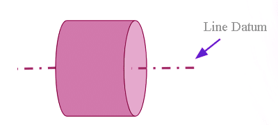
- Line Datums: Define the position of a line on the part’s surface, eliminating two degrees of freedom.
- Plane Datums: Specify the location of a plane on the part’s surface, removing three degrees of freedom.
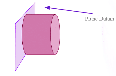
For instance, in a gearbox housing, the primary datum could be the bottom flat surface, the secondary datum the front face, and the tertiary datum the rear mounting points. Additionally, datums can be classified as planar, axial, or complex, depending on whether they consist of flat surfaces, cylindrical features, or more irregular shapes.
Datum vs. Datum Feature
Datum: A theoretical reference point, line, or surface from which measurements and tolerances are established. It serves as the starting point for the overall alignment and positioning of the part.
Datum Feature: The actual physical feature on the part (such as a surface, hole, or edge) selected to serve as the datum. This feature is used as the reference in both the drawing and manufacturing processes.
The distinction between these two concepts is crucial for understanding how measurements are referenced and applied. The datum feature is where the datum symbol is placed on the part, indicating the physical location for reference. In contrast, the datum itself is the abstract reference point that governs all measurements.
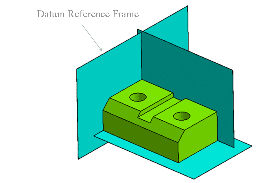
Datum Reference Frame (DRF)
The DRF is a coordinate system to define the location and orientation of a part in space, based on the primary, secondary, and tertiary datums. It defines the relationship between the part’s geometry and the coordinate system. As a result, this ensures that measurements and tolerances apply consistently throughout manufacturing and assembly.
Notation of Datums
In GD&T notation, specific symbols represent datums, helping to guide alignment and referencing of the part. The most common notations include:
- Datum Symbol (⊥): Placed next to the datum feature on engineering drawings to indicate it serves as the reference for measurements.
- Feature of Size: When a datum is in light of on a feature of size, like a hole or slot, the notation specifies the size and location of that feature.
- Datum Target: For irregular parts, datum targets are marked with a symbol featuring a target in the drawing, specifying a smaller, defined point, line, or surface for reference.
By correctly classifying and notating datums, manufacturers can interpret them precisely, ensuring more accurate and consistent part production.
Datum Targeting and Applications
Datum targeting defines small, discrete points, lines, or areas on a part as reference locations for measurements, instead of using continuous features like flat surfaces or holes. For example, in the manufacturing of turbine blades, datum targets are chosen at specific points on the blade to ensure accurate measurements, despite its complex shape. This method works well for parts with uneven or non-prismatic shapes that are difficult to reference with traditional datums.
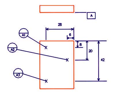
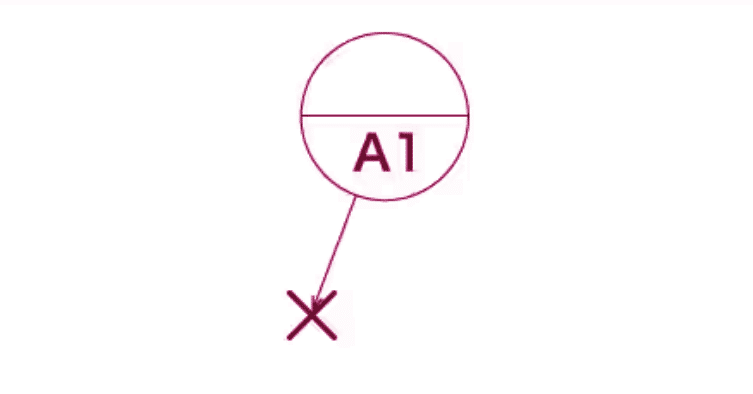
Steps for Using Datum Targets:
- Identify Irregular Features: Look for parts that have uneven or non-prismatic shapes, such as complex castings or components with contours.
- Select Specific Points or Areas: Choose smaller, defined points, lines, or surfaces on the part to act as the reference for measurements.
- Mark Datum Targets on the Drawing: Indicate the chosen targets on the engineering drawing using the appropriate symbols, such as a target symbol for a point or a line.
- Use in Measurement: During manufacturing or inspection, align the part using the datum targets. These reference locations help ensure that the part is measured accurately and consistently, even if the part’s geometry is irregular.
In addition, datum targeting finds wide use in industries such as aerospace, automotive, and machinery, where precise alignment and assembly of complex parts are essential. Key applications include:
- Complex and Irregular Shapes: For parts with features that can’t be measured from a single plane or axis, datum targeting allows referencing from specific, defined points.
- Assembly and Positioning: During assembly, datum targets help ensure consistent alignment, reducing the risk of misalignment or fit issues.
- Inspection and Quality Control: Datum targets play a crucial role in quality control by providing precise reference points for measuring the part’s accuracy.
Datum Vs. Tolerances
While both datum and tolerances are essential for ensuring part accuracy, they serve distinct purposes and influence each other in different ways.
| Aspect | Datum | Tolerances |
| Purpose | Measurement reference point | Acceptable variation limits |
| Role | Alignment & Positioning | Ensures function despite variations |
| Function | Guides measurement & alignment | Controls acceptable deviations |
| Assembly Impact | Ensures proper part alignment | Allows for minor variations in fit |
| Types | Planar, axial, complex | Dimensional & geometric |
| Quality Control | Inspection reference | Defines acceptable deviation limits |
As discussed earlier, a datum acts as a reference point, line, or surface from which all measurements and tolerances are established. In GD&T, datums help maintain consistency during production and align components within assemblies. In contrast, tolerances define the acceptable limits of variation for a part’s features, ensuring they remain within functional limits despite minor deviations during manufacturing. While dimensional tolerances focus on the acceptable range of measurements like length or width, geometric tolerances address variations in the shape, orientation, or position of features such as flatness or roundness. As such, datums and tolerances ensure parts fit and function properly within their assemblies. In short, a datum might define the precise location of a hole in a part, while the tolerance would specify how much the hole’s position can vary without affecting function.
Datum in 3D Modeling (CAD)
In contrast to GD&T, where datums define physical measurements and tolerances, in 3D modeling (CAD), a datum primarily serves as a reference for positioning and aligning components within the digital model. Below are the main roles of datum:
- Reference for Positioning and Dimensions: A datum ensures correct alignment and precise dimensions of the model.
- Foundation for Modeling and Editing: A datum serves as a reference to maintain geometric relationships, especially when handling complex models.
- Data Exchange and Compatibility: Datum consistency ensures model readability and editability when exchanging models between different CAD systems.
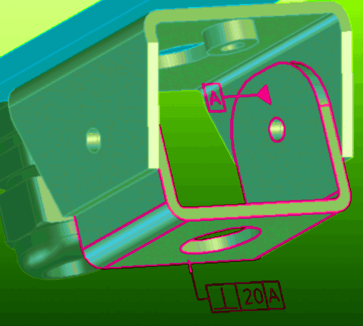
Types of Datum in 3D Modeling
- World Coordinate System (WCS): The global reference frame for all points and features.
- User Coordinate System (UCS): A local system used for specific modeling tasks.
- Local Coordinate System: A reference system for individual objects or features.
Applications of Datum in 3D Modeling
- Modeling Reference: A datum establishes the initial position and orientation of the model.
- Assembly and Constraints: Ensures proper alignment and positioning of parts during assembly.
- Measurement and Annotation: Ensures the accuracy of dimensions and geometric relationships.
Conclusion
In general, datums are fundamental to ensuring accurate alignment, positioning, and measurement in GD&T, manufacturing, and 3D modeling. Proper classification, application, and notation of datums prevent errors and ensure consistency. As industries evolve with advanced CAD tools and precision manufacturing methods, understanding how to use and interpret datums becomes increasingly critical.
Additionally, at Ancastings Precision, we use accurate datum systems to ensure that every product is made to the highest standards. By focusing on precise alignment and measurements, we ensure that our products meet exact specifications and work reliably, whether in fields like aerospace, automotive, or machinery. Please feel free to contact us or ask for an instant quote if you have any question.
FAQs
A datum is a reference point, line, or surface used to establish the origin for measuring and locating features on a part.
Datums provide a consistent reference for measurements, ensuring parts are aligned and manufactured accurately.
A datum is a reference point for measurements, while a tolerance defines the allowable variation in a feature’s dimensions or geometry.
Datums are represented by a specific symbol, often a letter, placed next to the datum feature on the drawing.
Datums should be chosen based on the most stable, functional, or critical features of a part to ensure proper alignment and positioning.
Symbols such as True Position, Perpendicularity, Parallelism, and Flatness typically require a datum for accurate measurement and alignment.