
When you machine 6061 or 7075 aluminum gas distribution panels, the worst thing that can happen is a single built-up edge (BUE) scratch appearing right when you’re holding a 0.2µm mirror finish. One scratch and the entire plate is scrap — no rework, no salvage. For semiconductor gas panels, where surface finish and contamination control are non-negotiable, BUE is the defect that keeps production managers up at night.
This article is not a textbook overview. It’s a working guide based on real machining practice for semiconductor-grade aluminum components.
What Actually Happens When BUE Forms on Aluminum
Aluminum is soft. Under cutting pressure, the material at the tool tip doesn’t shear cleanly — it smears. At the micron level, aluminum particles cold-weld to the cutting edge, forming a lump that grows, breaks off, and reforms. That lump is your built-up edge.
The problem is what happens next. The BUE changes the effective geometry of your tool. It dulls the rake face, increases cutting forces, and drags across the workpiece like a tiny plow. On a gas distribution panel with a 0.2µm Ra requirement, that drag leaves a scratch or a smeared patch that fails inspection. If a BUE fragment breaks loose, it can embed in the surface or become a loose particle — both are contamination risks in a cleanroom environment.
For semiconductor parts, the tolerance is usually ±0.01mm on gas ports and sealing surfaces. A BUE that shifts the tool by even a few microns will throw that off. And unlike a cosmetic defect on a general industrial part, a semiconductor gas panel with a compromised sealing surface is a leak risk in the fab.
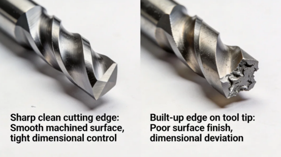
The Four Conditions That Cause BUE (And How to Control Them)
BUE doesn’t happen randomly. It forms when four conditions line up: high adhesion, wrong tool geometry, wrong cutting parameters, and poor chip evacuation. Control any one of them and you reduce the risk. Control all four and you eliminate it.
1. Aluminum’s Adhesion Problem
Aluminum has a high chemical affinity for most tool materials. At cutting temperatures — even with coolant, the tip can hit 400–600°C — aluminum softens and bonds to the tool through a mix of mechanical interlocking and micro-welding. This is not a lubrication issue alone. It’s a material science problem: you need a tool surface that aluminum doesn’t want to stick to.
2. Tool Geometry: Rake Angle and Edge Sharpness
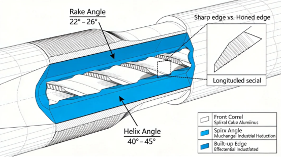
If your rake angle is too small, the chip doesn’t flow away cleanly. It curls back into the cutting zone, increases contact time, and gives the aluminum more opportunity to weld to the edge. For aluminum, you want a high positive rake — typically 22° to 26° for finishing tools. A sharp edge also matters. Honed or radiused edges that work well on steel will promote BUE on aluminum because they rub instead of cut.
High-helix tools (40° to 45°) help lift chips out of the cut. This is not a preference — it’s a requirement for deep cavities and narrow gas channels where chips would otherwise pack into the cut.
3. Cutting Parameters: Don’t Rub, Cut
The most common mistake in aluminum finishing is running too slow. When your feed per tooth is too low, the tool rubs instead of shears. Rubbing generates heat without removing material cleanly, and that heat accelerates BUE formation.
For finishing passes on semiconductor aluminum parts, a starting point that works:
| Parameter | Range for Aluminum Finishing |
| Spindle speed | 10,000–18,000 RPM (depends on tool diameter) |
| Feed rate | 80–150 mm/min semi-finish; 20–50 mm/min finish |
| Depth of cut | 0.02–0.10 mm finish |
| Coolant | High-pressure through-tool or flood |
These numbers are not universal. They depend on your tool diameter, flute count, and machine rigidity. But the principle is: keep the tool cutting, not rubbing.
4. Chip Evacuation: If Chips Stay, BUE Grows
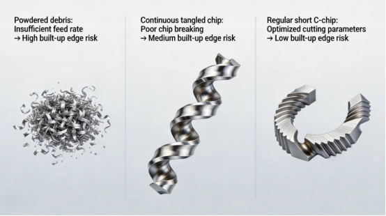
A chip that stays in the cut gets recut. Recutting generates heat, and heat plus aluminum equals adhesion. In deep gas channels or pocket features, chips can pack into the cavity and act like a abrasive slurry against the tool.
Use through-tool coolant or air blast to clear chips. For deep cavities, trochoidal or adaptive milling paths keep chip loads consistent and prevent packing. Aluminum-specific chipbreakers produce short, broken chips instead of long stringy birdsnests that wrap around the tool.
Tooling That Actually Prevents BUE
DLC Coatings: The Current Standard
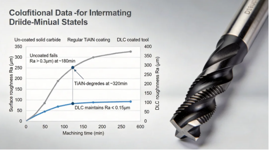
Diamond-Like Carbon (DLC) coatings are the most effective commercially available solution for aluminum BUE. The coating has a low friction coefficient, chemical inertness, and high hardness. Aluminum doesn’t want to bond to it.
Tungaloy’s DS2000 series is one example. The DLC coating is designed to suppress welding and maintain a sharp edge. Tool life in aluminum finishing can extend 15–20% compared to uncoated or standard TiAlN tools. Surface finish improves from around 0.2µm Ra to below 0.15µm Ra in many applications.
For semiconductor parts, DLC is not just about tool life. It’s about consistency. A tool that holds its edge longer produces more parts within tolerance before a tool change. That reduces setup variation and scrap.
Polished Carbide: Still Valid for Some Jobs
For certain finishing operations, a polished uncoated carbide tool can work. The polished rake face reduces the mechanical grip that aluminum uses to adhere. Look for tools with a high polish on the rake and flank faces, sharp edges, and positive rake geometry.
The trade-off is tool life. Polished carbide will not last as long as DLC in production. But for small batches or prototyping, it can be a cost-effective option if you manage speeds and feeds carefully.
Coolant and Lubrication: More Than Just “Lubricity”
In aluminum machining, coolant does two jobs: cool the cutting zone and prevent micro-welding at the tool tip. The second job is where most coolant strategies fail.
When aluminum cold-welds to the tool tip at the micron level, it starts as a tiny adhesion point. If the coolant can’t penetrate that interface, the adhesion grows. You need a fluid that forms a pressure-stable film between the tool and the chip. That means:
·Good lubricity under high pressure
·Neutral to slightly alkaline pH (aluminum is amphoteric — acidic or strongly alkaline fluids can stain or oxidize the surface)
·Low residue after drying, especially for cleanroom parts
·Anti-adhesion additives that specifically target aluminum
Water-based coolants can work if formulated for aluminum, but they need to be managed carefully. Concentration, pH, and tramp oil control all affect performance. For semiconductor parts, oil-based or specially formulated water-miscible coolants are often preferred because they leave less residue and provide better lubricity at the cutting edge.
High-pressure through-tool coolant (50–70 bar) is worth the investment for deep holes and channels. It clears chips and delivers fluid exactly where the heat is generated.
Cleanroom Contamination: The Hidden BUE Problem
Most BUE discussions focus on surface finish and tool life. For semiconductor gas panels, there’s a third issue: particles.
When BUE breaks off, it doesn’t just scratch the surface. It leaves fragments. Some embed in the aluminum. Some become loose debris. In a cleanroom, loose particles are a contamination source. Embedded particles can be released later during gas flow or thermal cycling.
This is why semiconductor machining cells need to be separated from general machining. Cutting fluids, chip handling, and cleaning processes all have to meet cleanroom-compatible standards. After machining, parts need vacuum or ultrasonic cleaning with particle testing to verify cleanliness. A part that passes dimensional inspection but fails particle count is still scrap.
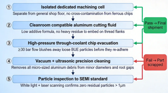
A Real Example
A manufacturer of semiconductor wafer processing modules was machining A6061 module plates. They were using standard aluminum end mills and getting frequent tool breakage and surface finish failures. The problem was BUE — aluminum welding to the tool, changing geometry, and causing chatter and scratches.
They switched to tools with optimized aluminum geometry and DLC coating. Surface roughness dropped from 0.20µm to below 0.15µm Ra. Tool life increased 15–20%. Most importantly, BUE-related defects disappeared. The parts passed cleanroom particle testing consistently.
The lesson: BUE prevention is not a single fix. It’s a system. Tool, coating, parameters, coolant, and chip evacuation all have to work together.
What to Do Next
If you’re machining aluminum gas distribution panels and fighting BUE, start with these three actions:
1.Check your tool geometry. If your rake angle is below 20° or your tool is honed rather than sharp, you’re already at risk. Switch to an aluminum-specific tool with high positive rake and a polished or DLC-coated surface.
2.Verify your finishing parameters. Calculate your actual feed per tooth. If it’s below 0.05mm per tooth on a finishing pass, you’re likely rubbing. Increase feed until you see clean chips, not dust.
3.Look at your chip evacuation. If you see chips recutting or packing in pockets, fix that before you change anything else. Through-tool coolant or air blast is not optional for deep features.
BUE is preventable. But it requires treating tooling, parameters, and contamination control as one system, not three separate problems. For semiconductor work, that system has to be tight enough to hold 0.2µm finishes and pass particle tests — every part, every batch.