
In precision manufacturing, CNC machining tolerances play a critical role in ensuring parts meet the required specifications. Understanding tolerances helps determine the allowable variation in part dimensions, balancing accuracy with cost efficiency. Thus, this article will delve into the essentials of CNC machining tolerances, ranging from definition to various types and standards. Additionally, it will explore some tips for selecting the right tolerance levels and factors that can influence tolerance decisions. Whether you’re designing complex components or seeking reliable manufacturing services, this guide provides the foundation you need to make informed choices.
What are CNC Machining Tolerances?
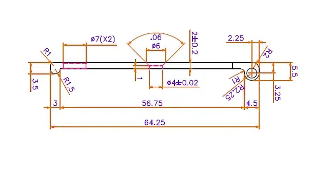
CNC machining tolerances refer to the allowable deviation from the exact dimensions specified in a part’s design or blueprint. In other words, they define the range within which the actual dimensions of a manufactured part can vary without affecting its functionality or performance. These tolerances are crucial in CNC machining, as they ensure that parts fit together correctly and operate as intended, while also accounting for the inherent limitations of the machining process.
Tolerances are typically specified as a plus/minus value, ±0.01 mm, indicating the acceptable variation in the final dimensions. Tight tolerances lead to higher precision but often increase the cost and complexity of the machining process. On the other hand, looser tolerances may reduce costs but can compromise the functionality of the machined parts.
Overall, CNC tolerances are essential for balancing precision, performance, and manufacturing efficiency in various industries.
Types of Tolerances in CNC Machining
In CNC machining, tolerances consist of several types based on the aspect of the part they affect. These tolerances ensure precision in different dimensions and features of a part. Here’s an overview of these specific tolerance types:
1. Standard Tolerances
Standard tolerances refer to industry-accepted tolerances acting on general parts that are specified by the international organizations, including ISO, ANSI, and ASME. These are usually predefined based on the machining process, material, and the size of the part. Common values for standard tolerances are typically around ±0.1 mm to ±0.005 mm, depending on the machining process.
2. Limit Tolerances
Limit tolerances specify the maximum and minimum allowable dimensions for a part. Instead of a nominal dimension with a plus/minus variation, limit tolerances are given as two specific values. For instance, a shaft could have a limit tolerance of 20.05 mm to 20.10 mm, meaning the shaft must fall within this size range.
3. Unilateral Tolerances
In unilateral tolerances, the permissible variation is allowed only in one direction from the nominal dimension, either positive or negative. For example, a part dimension of 50 mm with a tolerance of +0.1 mm/-0.0 mm means the part can be between 50.0 mm and 50.1 mm, but no smaller than 50.0 mm.
4. Bilateral Tolerances
Bilateral tolerances allow variations in both the positive and negative directions from the nominal dimension. For example, if a part has a dimension of 100 mm with a tolerance of ±0.05 mm, the actual dimension can range between 99.95 mm and 100.05 mm.
5. Geometric Dimensioning and Tolerance (GD&T)
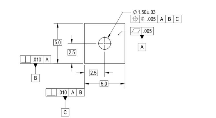
GD&T is a standardized system that can define and communicate tolerances for the shape, orientation, and position of features on a part. In addition to the dimensions, it also can focus on the geometric features of the part, such as flatness, cylindricity, and true position. Moreover, GD&T symbols can represent various tolerances to ensure precise communication and functionality between design, manufacturing, and inspection.
6. Runout Tolerance
Runout tolerance controls the allowable deviation of a surface as it rotates around a central axis. It ensures that rotating parts like shafts or gears maintain uniformity. There are two types of runout:
- Circular Runout: Controls variation of a surface in one rotational position.
- Total Runout: Maintains the entire surface variation throughout a part’s full length when rotated.
7. Form Tolerances
Form tolerances control the shape of individual features on a part with height gauges and calipers. These include:
- Flatness: Ensures a surface does not deviate from a perfectly flat plane.
- Straightness: Regulates the linearity of a surface or axis.
- Roundness: Specifies how much a cylindrical or spherical surface can deviate from being perfectly round.
- Cylindricity: Ensures the entire surface of a cylinder is uniformly round along its length.
8. Location Tolerance
Location tolerance ensures the exact positioning of features, such as holes, slots, or pins, relative to other features or datum references. The most common example is true position, which defines the permissible deviation of a feature’s center point from its exact intended location.
9. Orientation Tolerance
Orientation tolerance controls the angular relationship between features, ensuring proper alignment. Common orientation tolerances include:
- Parallelism: Ensures two features are parallel to each other.
- Perpendicularity: Maintains one feature that is 90 degrees from another.
- Angularity: Controls the angle between two features that are not perpendicular or parallel.
10. Profile Tolerances
Profile tolerances regulate the form and orientation of a surface. These include:
- Profile of a Line: Controls the shape of a feature in a 2D cross-section.
- Profile of a Surface: Ensures the 3D shape of a surface conforms to the design intent, within a specified tolerance zone.
Each of these tolerance types plays a specific role in ensuring that machined parts meet their requirements. Moreover, using the right tolerance is essential for balancing precision, manufacturability, and cost.
Typical Standard Tolerances
Typical CNC standard tolerances vary depending on the machining process, material, and the required precision for the specific part. Below are typical tolerance ranges for different CNC processes:
| Engraving | ± 0.005″ or 0.13 mm |
| Lathe | ± 0.005″ or 0.13 mm |
| Milling (3-axis) | ± 0.005″ or 0.13 mm |
| Milling (5-axis): | ± 0.005″ or 0.13 mm |
| Rail Cutting Tolerances | ± 0.030″ or 0.762 mm |
| Router | ± 0.005″ or 0.13 mm |
| Router (Gasket Cutting Tools) | ± 0.030″ or 0.762 mm |
| Screw Machining | 0.005″ or 0.13 mm |
| Steel Rule Die Cutting | ± 0.015″ or 0.381 mm |
| Surface Finish | 125RA |
In general, CNC machining tolerances reflect the level of precision most machines can reliably achieve without additional time or cost.
Terms for Machining Tolerances
Understanding these terms is essential for communicating the precision requirements in CNC machining. Below are some common terms for CNC machining tolerances.
- Actual Size: The measured size of a feature after machining. It indicates the real dimensions of the part, which may vary from the intended size due to manufacturing processes.
- Basic Size: The nominal or theoretical size from which limits of size are established. It serves as a reference point for determining tolerances and deviations.
- Datum: A reference point, line, or plane on a part that serves as a basis for measurement. Datums are crucial for ensuring consistency and accuracy in machining and assembly.
- Deviation: The difference between the actual size and the basic size. Deviation indicates how much a feature strays from its intended dimension, which can be either positive or negative.
- Limits: The maximum and minimum sizes permissible for a feature, defining the tolerance range. Limits help ensure that parts fit together correctly and function as intended within specified parameters. There are two specific values: the upper limit and the lower limit.
Tips for Choosing Tight Tolerances in Machining
Choosing tight tolerances in machining is a critical decision that can impact the performance of the part. Here are some tips to consider when selecting tight tolerances:
1. Understand Application Requirements
Assess the functional requirements of the part. Tight tolerances are essential for components that will fit together or interact with other parts, thus ensuring that the tolerances align with the part’s intended use.
2. Consult with Engineers and Designers
Collaborate with engineers and designers to determine the minimum tolerances needed. They can provide insights into which features are critical and which can tolerate more variation.
3. Evaluate Manufacturing Capabilities
Review the capabilities of the CNC machines and tools. Some machines can achieve tighter tolerances than others. Therefore, ensuring that the equipment can consistently produce parts within the specified tolerances without compromising quality.
4. Consider Material Properties
Different materials behave differently under machining conditions. Harder materials may require looser tolerances due to tool wear and thermal expansion, while softer materials may allow for tighter tolerances. As such, it should choose the materials according to the material’s characteristics.
5. Factor in Cost Implications
Tight tolerances often lead to higher production costs due to increased machining time, tool wear, and potential rework. Weigh the benefits of tight tolerances against the additional costs and consider whether the increased precision is worth the expense.
6. Account for Tolerance Stack-Up
Evaluate how tight tolerances on individual components may affect overall assembly. Tolerance stack-up can lead to cumulative deviations that may exceed acceptable limits. Use tools like tolerance analysis to predict and mitigate stack-up issues.
7. Use GD&T for Clarity
Apply GD&T to define the required tolerances clearly. GD&T symbols help specify not just dimensions but also the allowable variations in form, orientation, and location, reducing ambiguity.
8. Perform Prototype Testing
If possible, produce a prototype or a small batch of parts to test the machining process and validate the selected tolerances. This can help identify potential issues before full-scale production.
By carefully considering these factors, you can make informed decisions about the tight tolerances needed in machining, balancing precision with practicality and cost-effectiveness.
Ancastings’s CNC Machining Services
Ancastings Precision is committed to delivering parts that meet stringent tolerance requirements. Our standard tolerances typically range from ±0.1 mm to ±0.005 mm, depending on the machining process and material used. Additionally, Ancastings offers comprehensive CNC machining services tailored to meet a variety of industrial needs. Specializing in precision machining, we use advanced CNC technology to produce high-quality parts and components for industries such as aerospace, automotive, medical, and consumer electronics. Moreover, our services include CNC milling, turning, and grinding, with capabilities to handle both prototype and production runs.