CNC-machined plastic parts can show all kinds of unexpected issues—warping, distorted pockets, out‐of‐round features, even marks from clamping. The tricky part is figuring out what each problem really is and what its base is. In this blog post we will break down the 10 most common deformation types in plastic and how to prevent them in practice.
1. Bowing & Warping of Thin Walled Plastic Parts
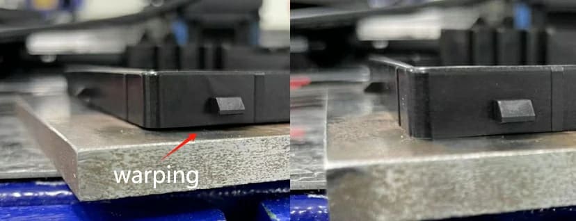
What Bowing & Warping Look Like in CNC Machined Plastic Parts?
Warping appears as sagging centers, lifted corners or twisted geometries. These distortions typically appear immediately after removing clamping forces. This visibly ruins the component’s flatness.
Main Causes of Bowing & Warping
- Release of residual stress during material removal.
- Unbalanced cutting and uneven wall thickness (±0.05 to 0.1 mm warpage common in unsupported areas).
- Heat buildup from aggressive passes or poor chip evacuation.
- Inadequate fixture support particularly under thin sheets.
Design & Material Precautions for Warping Control
- Maintain uniform wall thickness and avoid abrupt transitions to minimize stress.
- Prefer cast stock; lower stress materials resist deformation better than extruded options.
- Add gussets or ribs to support large flat surfaces; avoid unsupported areas exceeding 80 to 100 mm across for most engineering plastics.
Machining & Fixturing Solutions for Warping
- Utilize a “flip” machining strategy to remove material symmetrically from both faces.
- Support thin sections with vacuum fixtures or full surface support fixturing that matches the part profile
- Take multiple light finishing passes using sharp, positive rake tools.
- Use air blast cooling to prevent heat buildup.
For thin covers & panels, our team at ANCASTINGS often uses custom vacuum fixtures and balanced flip machining routines to control deformation early in the process.
Related Blogpost: How to Choose the Right CNC Fixture
2. Bending & Twisting of Long Bar- or Beam Type Plastic Parts
Visual Indicators of Bending & Twisting
Thin walled plastic parts mostly show curled edges, slight twisting or central sagging. These distortions typically become apparent once the workpiece is unclamped and allowed to relax freely.
Main Causes of Bending & Twisting
- Low stiffness in long, slender plastic parts makes small cutting forces produce measurable curvature.
- Axial residual stress in extruded rods causes the part to bend or rotate after material removal.
- Lateral forces from profiling push flexible plastics permanently out of line.
- Long unsupported spans permit mid section deflection.
Geometry & Setup Precautions to Limit Distortion
- Use practical length‐to‐thickness ratios; plastics mostly deform when exceeding 20:1 to 30:1.
- Add stress relief grooves where significant material removal occurs.
- Support long parts (above 150 to 250 mm) with steady rests.
- Select straight, stress‐relieved stock to minimize inherent distortion.
Machining Strategies to Reduce or Correct Distortion
- Apply a rough rest finish sequence to stabilize internal stresses.
- Use climb milling with conservative radial engagement to reduce lateral cutting forces.
- Maintain multiple support points to keep long parts aligned.
- Consider post machining straightening or low temperature annealing for high straightness components.
3. Dimensional Drift & Size Change After Machining
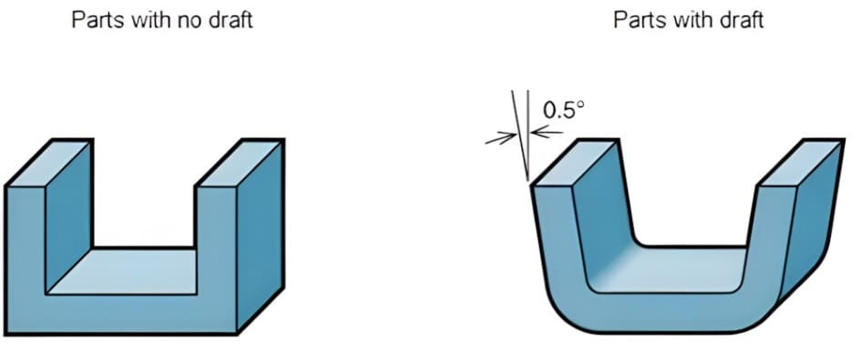
What Dimensional Drift Looks Like in CNC Machined Plastic Parts
Plastic parts initially meet tolerance during inspection but gradually shift out of specification over hours or days. This delayed dimensional change often appears as expansion, shrinkage or subtle warping.
Primary Causes of Post Machining Size Change
- Viscoelastic relaxation releases internal stress gradually. This causes slow dimensional movement.
- High thermal expansion coefficients make plastics sensitive to minor temperature variations.
- Internal stress from extrusion causes bending or twisting when material is removed.
- Fluctuating shop conditions or improper storage accelerate post machining changes.
Design & Material Precautions for Dimensional Stability
- Select high stiffness plastics like acetal or PEEK for critical dimensions.
- Avoid tolerances tighter than ±0.001″ unless functionally needed.
- Account for service temperature in tolerance stack up calculations.
- Use glass fiber reinforced grades to lower thermal expansion.
Process Controls & Stabilization Solutions
- Pre condition or anneal stock before finishing to release locked in stress.
- Allow parts to rest 12 to 48 hours between roughing & finishing.
- Qualify parts at a stable temperature and humidity before measurement.
- Store finished components in sealed packaging to prevent humidity induced drift.
4. Surface Dishing & Pocket Floor Deformation
How Dishing & Pocket Deformation Appear on Plastic Parts
In CNC milled plastic pockets, dishing appears as concave pocket floors, domed surfaces or thin sections bowing upward after release. These errors become visible when straight edges reveal gaps across large flat milled areas.
Main Causes of Dished Surfaces in Plastics
- Downward cutter pressure deflects flexible floors. This leaves extra material in the center.
- Aggressive removal on one side releases compressive skin stress which causes floors to bow.
- Poor chip evacuation traps heat, locally softening & expanding the pocket bottom.
Preventive Design & Setup Practices
- Avoid extremely thin unsupported floors; maintain thickness above 1.5 mm or use stiffening ribs.
- Design pockets with generous corner radii to reduce sudden tool engagement and stress.
- Ensure fixturing lets access to both sides for balanced material removal.
Cutting Strategy & Toolpath Solutions
- Use the largest possible tool diameter to maximize rigidity and minimize deflection.
- Employ spiral toolpaths or High Efficiency Milling (HEM) to maintain constant tool load.
- Perform a final light “spring pass” at full depth to remove remaining material.
5. Ovality & Out of Round Holes & Bosses
Typical Symptoms of Oval or Tapered Plastic Holes
Ovality typically manifests as press fit components being loose in one axis and tight in the perpendicular axis or precision bearings failing to seat correctly because of non circular geometry.
Causes of Out of Round Features in CNC Machined Plastics
- High clamping forces distort thin‐walled hubs which spring back to oval shapes upon release.
- Heat induced expansion causes holes to be cut undersized. This shrinks irregularly as they cool.
- Radial deflection of drills occurs easily in soft, flexible plastics which create lobed holes.
Design Precautions for Roundness Critical Features
- Increase wall thickness around precision bores to better resist clamping & cutting forces.
- Specify realistic geometric tolerances as plastics have higher deflection than metals.
- Orient critical bores away from high pressure clamping zones in the fixture design.
Machining & Inspection Solutions for Roundness
- Finish critical holes with single point boring or reaming rather than standard drilling.
- Use peck cycles and polished, slow spiral drills to evacuate chips and reduce friction heat.
- Measure roundness only after the part has fully stabilized at standard room temperature.
6. Local Indentation & Clamping Mark Deformation
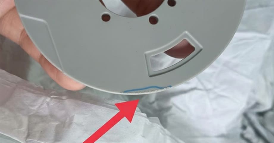
How Clamping Marks Affect CNC Machined Plastic Parts
Clamping marks in CNC machined plastics appear as dents, flats as well as shiny compressed bands. These marks can distort features like gasket grooves, sealing lands, or precise locating bosses. As a result leaks or misalignment may occur during use.
Main Causes of Clamping Induced Deformation
- Hard steel jaws concentrate load on small areas which plastically compresses softer polymers on release.
- Excessive clamp force on thin walls below 2 to 3 mm causes elastic bending and permanent creep.
- Long clamp duration during multi minute toolpaths lets viscoelastic plastics flow. This leaves residual indentations.
Fixturing Precautions To Reduce Clamping Damage
- Use vacuum fixtures or soft jaws to distribute holding force over a larger surface area.
- Support the part fully—particularly under thin sections—to prevent localized collapse.
- Define standard clamping pressures and strict torque limits appropriate for soft plastics.
Practical Solutions for Clamping Deformation & Recovery
- Machine parts in multiple setups with lighter clamping force instead of one aggressive hold.
- Include sacrificial tabs or clamping bosses outside the final part geometry.
- Consider post machining lapping or polishing to restore flatness on critical contact surfaces.
7. Chatter, Surface Waves & Shape Wandering
What Chatter & Shape Wandering Look Like in Plastics
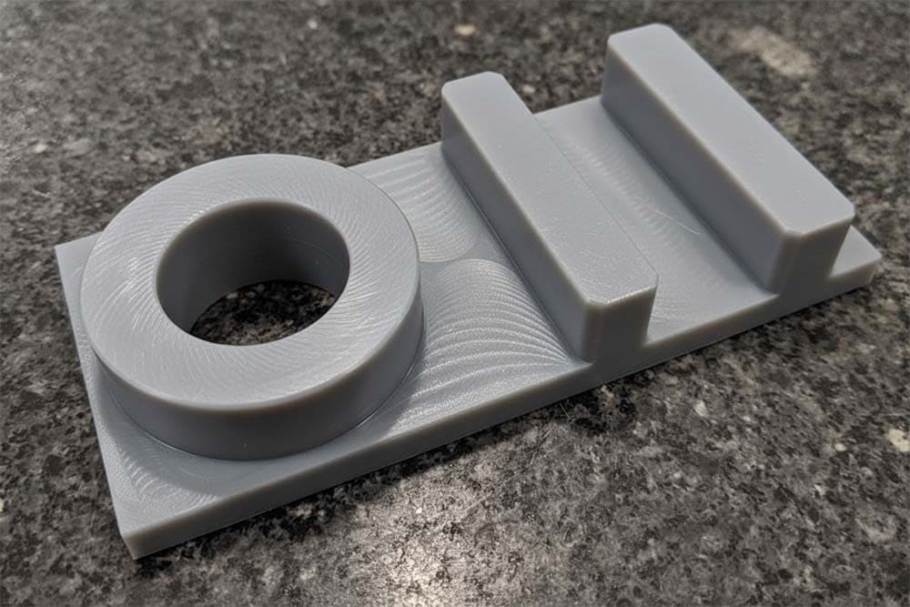
Chatter appears as wavy surfaces, ripples as well as an uneven finish on machined plastics. This vibration induced error also leads to dimensional wandering on long, slender features.
Causes of Vibration Driven Deformation in Machined Plastics
- Aggressive feed rates and high spindle speeds can excite natural frequencies which cause tool vibration.
- Inadequate workholding or part support fails to dampen vibrations especially in flexible, thin walled plastics.
- Dull tools or cutters not optimized for plastics increase cutting forces, inducing chatter.
Precautions in Tooling & Machine Setup
- Use sharp, high positive rake tools designed for plastics to shear material cleanly instead of pushing it.
- Minimize tool and holder overhang for maximum rigidity and reduced tool deflection.
- Apply solid, comprehensive workholding to dampen part vibration during machining.
Process Adjustments To Eliminate Chatter & Waves
- Switch to climb milling as it helps pull the workpiece into the cutter. This reduces deflection and vibration.
- Use toolpaths with constant engagement to keep cutting pressure consistent and minimize chatter.
- Systematically adjust spindle speeds and feed rates to move out of resonant frequency zones.
8. Moisture Induced Swelling & Shrinkage Deformation
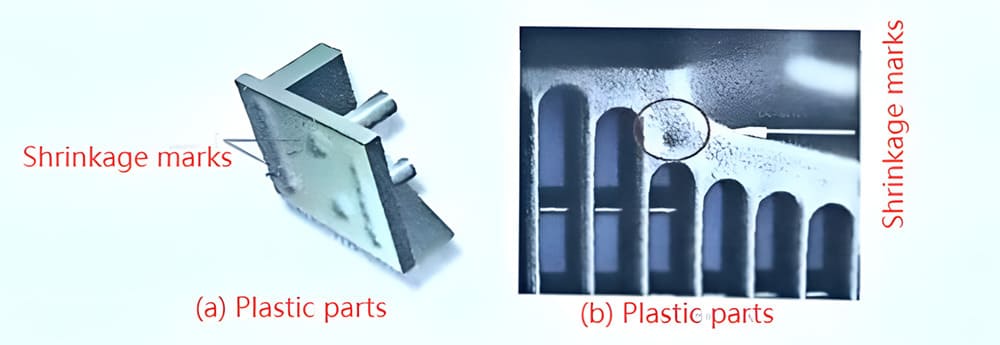
Moisture related deformation manifests as unexpected dimensional growth. This often causes tight tolerance nylon gears to seize or large flat plates to warp under fluctuating humidity.
Causes of Hygroscopic Swelling in CNC Machined Plastics
- High water absorption rates in hygroscopic plastics like Nylon (PA6/ PA66) cause volumetric expansion
- Dry machining followed by humid exposure causes swelling, especially in materials such as PEEK, nylon and PC blends.
- Uneven moisture absorption between a part’s core and surface introduces internal stress which bends or distorts thin sections.
Material & Storage Precautions Against Moisture Deformation
- Identify high absorption plastics early; Nylon 6 can absorb up to 8 to 9% moisture by weight at saturation.
- Store stock and semi finished components in sealed bags with desiccants to assure stability.
- Condition parts to expected service humidity levels before final sizing operations.
Machining & Measurement Solutions for Hygroscopic Parts
- Bake or pre dry stock per supplier datasheets to establish a stable starting point.
- Finish machine critical dimensions only after the part stabilizes at equilibrium moisture content.
- Define separate in-process & final inspection limits that account for expected in‐service swelling.
For hygroscopic plastics such as nylon or PEEK, ANCASTINGS takes extra steps to control dimensional change by pre‐conditioning material and finishing key features only after the part has stabilized at its service humidity.
9. Thermal Softening, Melting & Heat Affected Deformation
Visual Signs of Heat Induced Deformation in Plastics
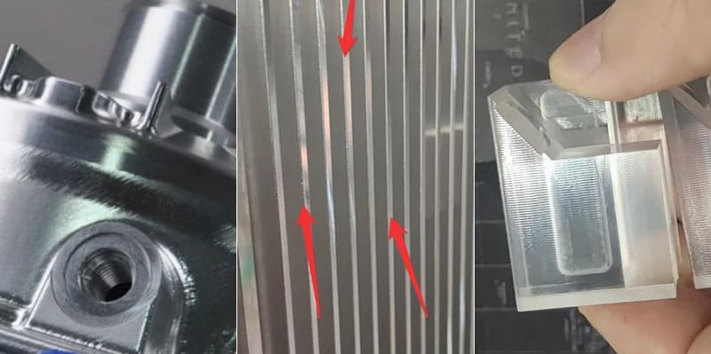
Heat damage in CNC machined plastics appears as smeared chips, glossy melt zones as well as raised lips along toolpaths. These thermal marks often emerge after unclamping, especially in parts made from low melting point materials.
Key Thermal Causes in CNC Machined Plastic Parts
- Excessive cutting speeds and aggressive feed rates create frictional heat exceeding the plastic’s softening point.
- Inadequate cooling leads to temperature buildup in deep pockets or small features.
- Poor chip evacuation traps heat in deep slots. This causes localized softening.
Preventive Measures in Material & Process Planning
- Choose materials with appropriate heat deflection temperatures; most engineering plastics show HDT values from 65°C to 150°C.
- Avoid high energy roughing on low melting point plastics like Polyethylene (PE) or Polypropylene (PP).
- Define maximum part temperatures in process sheets to prevent hidden internal stress.
Cooling & Toolpath Solutions for Thermal Control
- Use mist coolant or compressed air suited to the plastic grade for effective heat dissipation.
- Reduce step downs and step overs to minimize friction and heat buildup
- Program toolpaths with adequate chip evacuation paths and avoid recutting chips.
10. Creep, Cold Flow and Load-Induced Deformation
Recognizing Creep & Cold Flow in Plastic Components
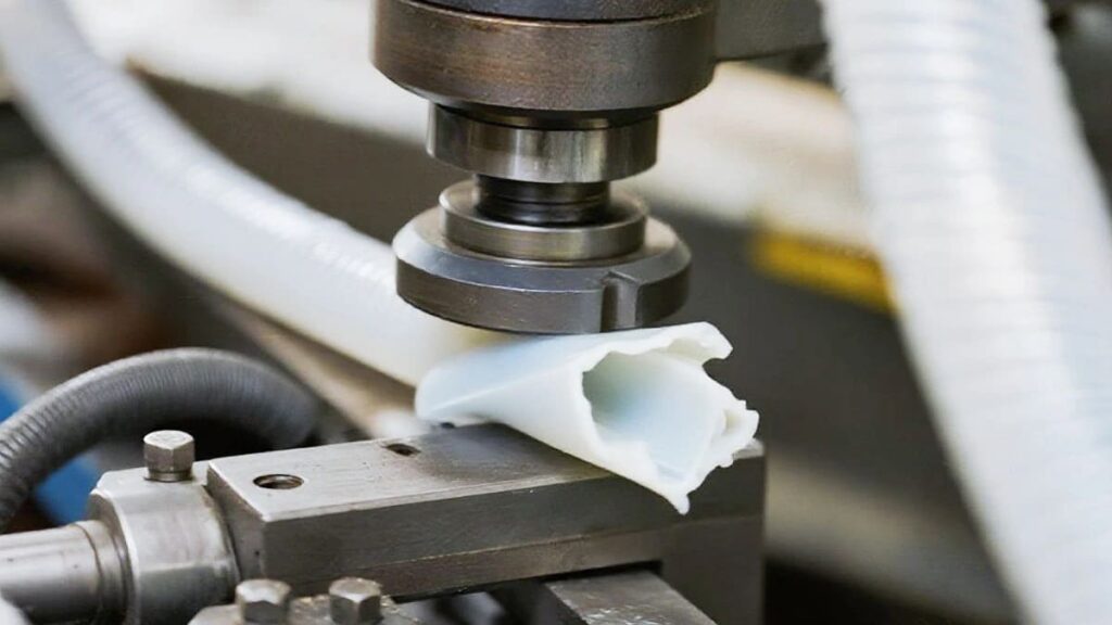
In CNC machined plastics, creep appears as slowly sagging flanges, distorted seal grooves and permanent deflection under constant assembly loads over weeks or months.
Fundamental Causes of Creep Deformation in Plastics
- Plastics exhibit time dependent viscoelastic behavior. This causes them to slowly deform under constant stress.
- Elevated service temperatures above 50‐60% of the material’s glass transition temperature significantly accelerate creep.
- Thin ribs, undersized sections as well as sharp internal corners concentrate stress which drives localized creep.
Design & Material Choices To Limit Creep
- Choose higher modulus, creep resistant polymers like Torlon, PEEK or glass filled grades for structural parts.
- Increase bearing areas and use large radii to better distribute mechanical stress and reduce point loads.
- Factor long term creep data from supplier datasheets into tolerance and clearance planning.
Machining & Assembly Solutions for Creep Control
- Avoid inducing extra residual stress during assembly by using torque limited fasteners or press fits.
- Validate long term performance with creep analysis or accelerated life tests for mission‐critical components.
- Install metal inserts or bushings (e.g., limiters) to handle high compressive loads.
How To Build a Deformation Resistant CNC Machining Workflow?
Building a reliable workflow starts with early risk assessment. Review material properties like thermal expansion and moisture absorption before cutting a single chip.
Always incorporate stress relief steps such as annealing stock and scheduling rest periods between roughing & finishing. Use balanced, low force workholding—like vacuum tables or soft jaws—to support parts without compressing them.
Crucially, select appropriate tooling; high positive rake cutters (10 to 20°) with polished flutes ensure clean shearing and efficient chip evacuation and this prevents heat buildup. Finally, validate processes with in‐process probing and controlled‐environment inspection to catch drift early.
At ANCASTINGS we use this same disciplined approach on every CNC plastic project. This combines modern equipment with experienced engineers so deformation risks are handled early instead of showing up at the end of the run.
Conclusion
Controlling deformation in CNC machined plastic parts needs optimization of process parameters, understanding about material behavior and implementation of proper fixturing strategies. Each deformation type demands particular preventive measures. Success lies in combining design foresight with disciplined machining practices.
For reliable, distortion‐free components, you can trust Ancastings’ expert CNC plastic machining services to assure your next project meets exact specifications.
Plastics have a higher thermal expansion rate which causes them to expand more from machining heat. They are also less rigid and deform more easily under cutting forces.
Softer plastics like UHMW, semi‐crystalline plastics and moisture‐absorbing ones like Nylon are most prone to warping because of their inherent properties and environmental reactions.
Base your tolerances on the material’s datasheet, considering its thermal expansion and moisture absorption properties. Avoid unnecessarily tight tolerances unless it is critical for the part’s function.
To minimize deformation, use sharp tools and stress‐relieved materials with appropriate feeds and speeds. Design parts with uniform wall thickness and use proper clamping methods to prevent stress. Annealing after machining can also help relieve internal stresses.